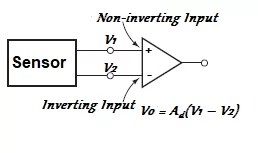
Most often than not, the signal from the sensor in a measurement and control or monitoring system is very small (one millivolt or less) and a key step in signal conditioning is amplification. Therefore, the sensor is often connected to the input terminals of an amplifier. The amplifier in this case can either be single-ended input or differential input type.
In a single-ended input amplifier, one of its input terminals is grounded as demonstrated in Figure 1.0 below and the output is the gain constant A times the input voltage:

For an amplifier with a differential input, it has non-inverting and inverting input terminals as illustrated in the figure below and ideally in this case, neither of the amplifier input is grounded and the output is the differential gain Ad times the difference between the input voltages.

Related articles:
- Causes of Ground Loops in Instrumentation & How to Avoid Them
- 4-20 mA Transmitters (2-wire, 3-wire and 4-wire Types)
- How Signal Processing Circuits are protected from high currents & voltages
- RTD 2, 3, 4 Wire Sensor Connections
- Features of Analog Signal Transmission

Leave a Reply
You must be logged in to post a comment.